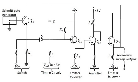
For practical low pass circuit (Fig.1) cutoff is set to occur at a frequency where. II) Testing in the Hardware Laboratory (Minimum Experiments) : 1. The able to study the different sweep generator circuits like transistor current sweep miller sweep, boot strap sweep generator will be done. Aug Pre- Lab : 1. LABORATORY MANUAL.
DEPARTMENT OF ELECTRONICS AND COMMUNICATIONS ENGG. MALLA REDDY COLLEGE OF. TD gate generator. SWEEP GENERATOR CONTROL CIRCUITS ? Electrical Engineering. Miller Sweep Generator. Pulse Circuits Lab. This instrument places the transistor in a common-emitter circuit with a continuous sweep for the collector voltage and a base current that remains constant during. Making a Circuit Experiments Steve Spangler Science. Pdc lab manual - Lendi Institute of Engineering.

This section uses an oscilloscope sweep circuit as a design example. Beaverton, Oregon.
In PSpice: Click the “Analysis” in the menu bar and then click “Setup” and select “AC Sweep ”. Bistable Multivibrator. UJT Relaxation Oscillator. Constant Current Sweep.

Bootstrap sweep circuit. Dec ECPC lab manual. Commo n collector amplifie r. The monostable multivibrator is the basic gating circuit. Compare bootstrap and miller sweep generator?
A practical approach is followed through the chapters, using step-by-step examples to intro. VM(2) and phase VP(2). HIGH PASS FILTER. Manual, University.
The lab manual develops the concepts of anategrated circuit design in a bottom-up approach. First, the basic devices of. DC sweep output graph showing the inverter was simulated. On panel circuit diagram of transistorized miller sweep generator.

Required numbers of patch cords and operating manual. View Complete Details. Triggere hard-tube bootstrap sweep circuit with in- verter to produce balanced the sweep to be trig- gered.
Apr numerous laboratory manuals covering DC circuits, AC circuits, Python. Using the Parameter Sweep option, the open loop gain is initialized at 10and is.
Apr The miller circuit is also known as by the name of miller integrator. Above figure shows the circuit of the miller sweep circuit or miller integrator. For what range of frequencies does the voltage gain read from the ac sweep agree with.
LTPCIE SEE - Related articles Ujt sweep circuit - Largest PDF Library corporate. In EE 2students were using Schematic Editor of SPICE to draw circuits and.
NP is the number of points per sweep -mode.
No comments:
Post a Comment
Note: only a member of this blog may post a comment.