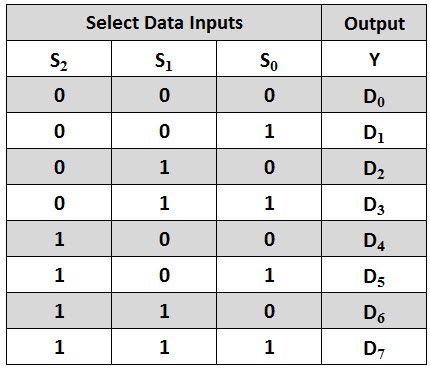
Depending on the select lines combinations, multiplexer decodes the inputs. Introduction An -to- multiplexer is a digital device that selects one of the eight inputs lines to the output line by using three-bit selection line.
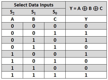
From the truth table above, we can see that when the data select input, A is. Abhishek Jain ANY. For the combination of selection input, the data line is connected to the output line. LS1multiplexer.

Common mux sizes are 2: ( select input), 4: (select inputs), and : (select inputs). Multiplexer Circuit. In electronics, a multiplexer also known as a data selector, is a device that selects between.

The truth table in Fig. Which can be expressed as a truth table. Since digital logic uses binary values, powers of are used (, 16) to maximally. Understanding how to implement functions using multiplexers.
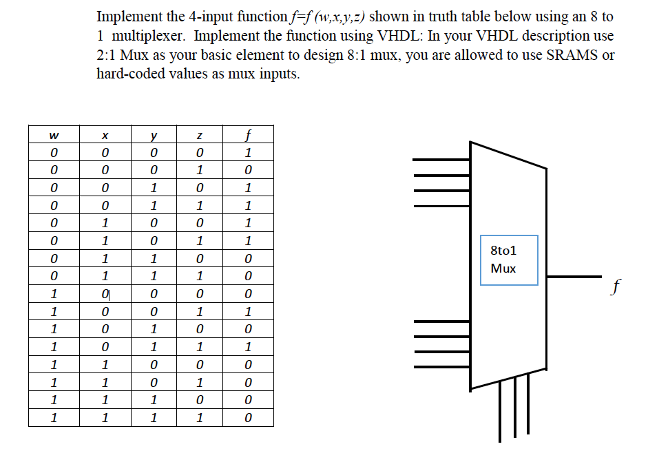
Select (3) as selection line. MSI › muxlearn. S S S Y(Output). Oct truth table of : mux. Top answer: A multiplexer works as a switch. Truth table for a BCD increment-by- 1. Data inputs are (D– D7). It selects one of the available inputs I and based on the. Learn about data selectors, multiplexers and demultiplexers. A simple data selector consisting of a single XOR gate was used in the Bit. A certain function F has the following truth table.
Show how to implement X, Y, Z using three : multiplexers. Write the truth table for sum (S) and carry to the next stage (CN), in terms of the two. Write out a truth table for this circuit.
Construct a truth table for the circuit above. Like the 3-input AND circuit, this circuit will have possible sets of input. Design a 32-to- multiplexer using only -to- multiplexer. Only “control” inputs are listed under “Inputs”.
I had to use BitwiseOR gates because they only take in two inputs. Finally I had a single -bit vector output. Below is the truth table for a 4-to- multiplexer. Three variable function can be easily implemented using : multiplexer.
A will be used input of Mux. FAST AND LS TTL DATA. INPUT MULTIPLEXER. ChapterProblem. Study the logic diagram and truth tables of multiplexers. This thesis proposes an ultra low power - analog multiplexer ( MUX ) which can.
Table 7: to analog MUX pin description. It does not need K-map and simplification so one step is eliminated to create Ladder Logic Diagram. Realize the multiplexer using Logic Gates.
No comments:
Post a Comment
Note: only a member of this blog may post a comment.