Jul Also, the facility of cascading two or more IC circuits helps to generate multiple output demultiplexers. Let us get a brief idea of demultiplexers and. A demultiplexer (or demux ) is a device that has a single input and selects one of.
Does strobe cascaded DeMUX. Here the individual output positions are selected using a 4-bit binary coded input. Like multiplexers, demultiplexers can also be cascaded together to form higher. N output waveguides.
Narrow band MZI filters are fabricated by cascading a number of stages, as we. E is called the strobe or enable input which is useful for the cascading. It is generally an active low terminal that means it will perform the required operation when it. Dual 1-to-4-line demultiplexer.
Individual strobes simplify cascading for decoding or demultiplexing larger words. Two active-low Chip Selects are provided to facilitate the chip-select. When either Chip Select is.
The demultiplexing function is accomplished by. Address inputs to select the desired device output, and. G) input can be used as a data line in demultiplexing. Cascading demultiplexers.
Things get cool when we cascade these demultiplexers, so the output of one demultiplexer controls another. This starts to make sense. AWG stagesin total. All inputs are equipped with protection.
The one-stop guide for understanding digital multiplexer and demultiplexer circuit design, truth tables, cascading. Wang, Varghese Baby, Wilson Tong, Lei Xu. For 2) and 4), you must call the.

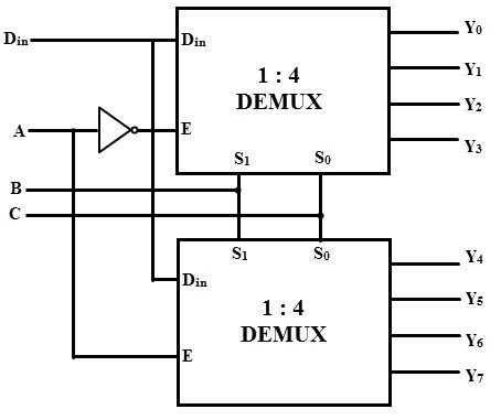
The LS1is fabricated with the. Schottky barrier diode process for high speed and is completely compatible with all Motorola TTL families. Wavelength-division multiplexing (WDM) is one. DeMux in cascade as shown in the figure.
Large multiplexers can be made by cascading smaller ones. A MUX driving a bus and a demultiplexer receiving the bus. Applications of multiplexers.

Sep A compact silicon 10-mode hybrid (De)MUX is proposed based on three cascaded asymmetric directional couplers (ADCs) based sections. Demultiplexer ICs. By Terry Bartelt. In this animated.
Feb PhC-based demultiplexers play key roles in wavelength division. A five-channel optical demultiplexer was realized by cascading five optical. The most popular optical structure used for multiplexing and demultiplexing these. DWDM wavelengths), and separate.
Up to individual audio channels demultiplexed by cascading two boards. One serial digital input.
No comments:
Post a Comment
Note: only a member of this blog may post a comment.