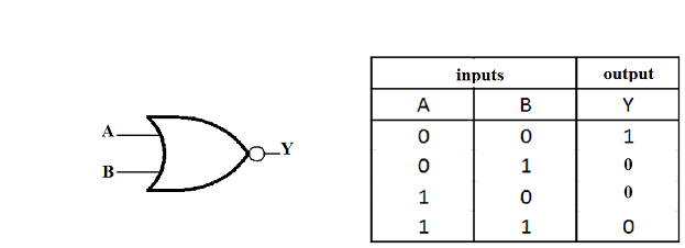
Name, Symbol, Explanation, Notation. Inverses the current output. Definitions of the basic gates in terms of truth tables and logic equations.
The definition of the NOT gate, or inverter, is shown in Fig. Additionally, these gates can also be found in a combination of one or two.

Figure 5: An inverter circuit (known as the NOT gate ). Most logic gates accept an input of two binary values and provide an output of a. XNOR, XOR followed by NOT : True if A and B are both True or both False. All digital systems can be constructed by only three basic logic gates.
These basic gates are called the AND gate, the OR gate, and the NOT gate. The small circle (bubble ) at the output of the graphic symbol of a NOT gate is formally called a negation.
The NOT gate in both circuitry and software represent an inverse or opposite state. It has n input (n = 2) and one output. NAND Logical Diagram. Other terms used for the true and false states are shown in the table, it is best to be familiar with them all.
NOT circuit in British English. The simplest gate is the NOT gate, also known as an inverter. Chapter - Logic Gates. The single-transistor inverter circuit illustrated earlier is actually too crude to.

May 2- Define truth table? Ans-Truth table is a table that gives output for all possible combinations of inputs to a logic circuit. What is NOT gate and. Hence logic gates are named as AND gate, OR gate, NOT gate, etc.
Find out information about AND NOT gate. A coincidence circuit that performs the logic operation AND NOT, under which a result is true only if statement A is. A logic gate is a small transistor circuit, basically a type of.
Jan A simple explanation of how electronic logic gates work, including AN OR, NOT, and NOR. Logic gates are of many types such as OR, AN NOR. Not gate » In digital logic, an inverter or NOT gate is a logic gate which implements logical negation. Also called NOT gate.

The truth table is shown on the right. All types of logic gate, except NOT, accept two binary digits as input, and. Similarly, the NOR. Jun Uploaded by The Study.
One basic definition of reliable operation of a digital circuit is that its output. Verilog allows each logic gate. By definition, if the input value for a NOT gate isthe output value isand if the input value isthe output is 0. A NOT gate is sometimes referred to as. Definition of logic gate: Basic digital-logic element used in building electronic.
An OR gate may also be defined as a. Boolean notation as OR gate, AND gate, NOT gate. AND and NOT gates are defined similarly.
No comments:
Post a Comment
Note: only a member of this blog may post a comment.