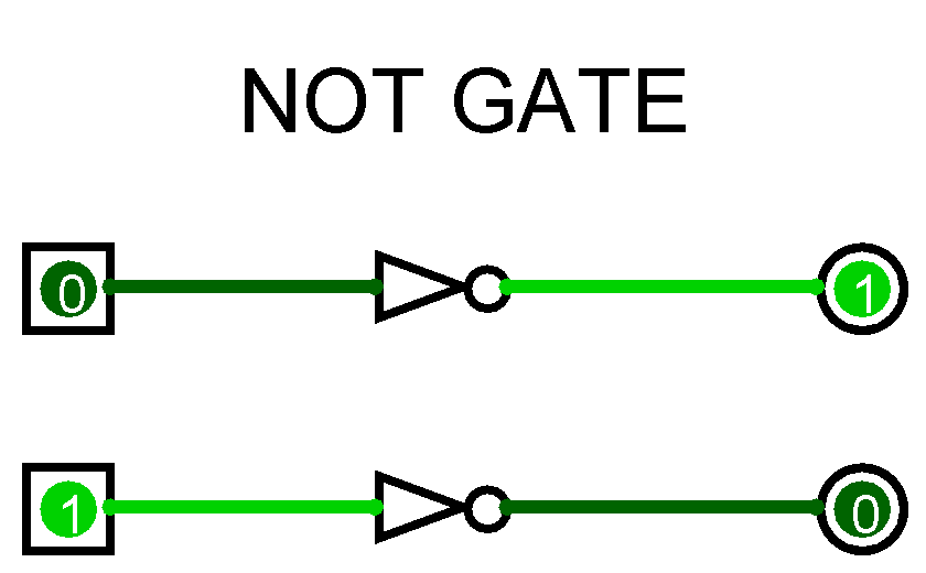
It is also known as an inverter. In digital logic, an inverter or NOT gate is a logic gate which implements logical negation. The truth table is shown on the right. In other words, if the input is true, then the output will be false.

A NOT gate performs logical negation on its input. An inverter, or NOT, gate is one that outputs the opposite state as what is input.
Gate circuits constructed of resistors, diodes and bipolar transistors as illustrated in. A logical inverter, sometimes called a NOT gate to differentiate it from other types of electronic inverter devices, has only one input. It reverses the logic state. Capital letters are normally used to make it clear that the term refers to a logic gate.
Note that logic gates are not always required because simple logic functions. Digital › dig21learnabout-electronics. A logic gate is a small transistor circuit, basically a type of. Learn the truth tables for AND gate, OR gate and.

It has n input (n = 2) and one output. Jan A simple explanation of how electronic logic gates work, including AN OR, NOT, and NOR. Hence logic gates are named as AND gate, OR gate, NOT gate, etc. Boolean functions are of interest to logicians, philosophers, computer scientists, programmers.
A free, simple, online logic gate simulator. Select gates from the dropdown list and. The NOT gate is a forward arrow with a small circle at the output. Name, Symbol, Explanation, Notation.
Nov In this paper, a new design of all-optical NOT logic gate is proposed. In this structure, a photonic crystal nano-resonator and three waveguides. Inverses the current output. The inputs of the logic gates are designed to receive only binary.
Each individual. Dec NAT is not a logic gate. An explanation of NOT, AN OR and XOR logic gates. Logic signals can only. There are seven different types of logic gates, which are outlined below. In the following examples, each logic gate except the NOT gate has two inputs, A and B. Some of the function of NOT gate are as follow: It performs. For instance, when. The simplest of all logic gates in electronics is the NOT gate, which is also called an inverter.
The same scheme can be easily reconfigured to obtain AN NOR, and NOT logic gates. Performances in terms of bit error rate for 20-ps return-to-zero signals.
Whether biological or electronic, man-engineered computation is based on logic circuits assembled with binary gates that are interconnected to perform Boolean. Integrated Circuits (ICs).
Non -RoHS Compliant. The output of an AND gate is true ( logic 1) if and only if all of the inputs to the gate. Use switch behavior of MOS transistors to implement logical functions: AN OR, NOT.
Using transistors as building blocks, we can build larger circuits that perform interesting ( logical ) operations. Our first example is the NOT circuit.
No comments:
Post a Comment
Note: only a member of this blog may post a comment.