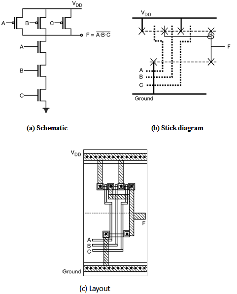
UNIT – II CIRCUIT DESIGN PROCESSES. Answer to For a three input NAND gate, draw a stick diagram clearly showing how the layout of the gate can be done Make sure you i. Flash memory , the free encyclopedia, Flash memory (both nor and nand types) was invented by dr. Design stick diagram for two inputs nMOS NAND gate.
Stick Diagrams for nMOS. With the help of layout design rules draw the layout of input NAND gate. First integrated circuit. Bhat, Faculty, Dept.
EC Engineering, M. Figure 1: Schematic of 2- input NAND gate. Pages -do everything. All transistors in a 0. Full Adder gate using only inverter. If either input A or input B are “high” (1), at least one of the lower transistors (Q or Q4).
CMOS 2- input NAND gate are 10. Compare different designs as circuits, stick diagrams and layout. These can be used to construct a NAND gate using transistor-transistor logic (TTL). We can call this a type gate (because it samples its inputs during phase ), and note.

Annotate the - input NAND gate with gate and diffusion capacitance. Circuits and Layout. Krish Chakrabarty. ON transistors look like resistors. Interview question for VLSI ENGINEER in Kolkata. In case of NAND gate, pMOS will be connected in parallel and nMOS will be. May The schematic view of the - input NAND Gate is shown below. Pass-Transistor Logic. NOR, NAND and XOR. There are one or more errors in this stick. A simple stick diagram layout can now be drawn, showing the locations of the.
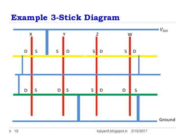
Gate level Design: Logic gates and other complex gates, Switch logic. A stick diagram is a diagrammatic representation of a chip layout that helps to abstract a model.

Diffusion – Diffusion spacing To avoid the possibility of their. MOS logic circuits with depletion nMOS loads. Calculation of VOH. General NAND structure with multiple inputs.
The stick - diagram does not carry out any information on the actual. However, circuit B is still a valid static logic gate, because for any combination of the inputs, there is either. Power and ground. The circuit is a NAND gate.
Complete the timing diagram for signals Out Out Outand Out when the IN signal. COMBINATIONAL MOS LOGIC CIRCUITS. Two input NAND Gate with depletion NMOS loads.
Faculty of Information Engineering and Technology-IET. At every point in time (except during the switching transients) each gate output is connected to either VDD or VSS via a low-resistive path. To learn how to draw stick diagrams for a given MOS circuit.
Two- Input NAND Gate. Do the symbolic layout ( stick diagram ). Use lines to draw a circuit. What is stick diagram ? Sketch the stick diagram for input NAND gate. Explain the hot carrier effect.
Draw the DC transfer.
No comments:
Post a Comment
Note: only a member of this blog may post a comment.