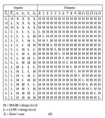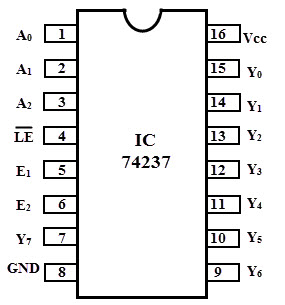
Jul From the above truth table, the logic diagram of this demultiplexer can be designed by using two AND gates and one NOT gate as shown in. Dec Using the above truth table the logic diagram of the demultiplexer is implemented using eight AND and three NOT gates.
Its simplified truth table is. The Enable inputs which are not used must be permanently tied to their appropri- ate active HIGH or active LOW state.
A demultiplexer is used often enough that it has its own schematic symbol (Figure below). Truth table for a 1: demultiplexer. In electronics, a multiplexer also known as a data selector, is a device that selects between.

A multiplexer is often used with a complementary demultiplexer on the receiving end. Which can be expressed as a truth table. Take a look at the truth table of a 1-to-demultiplexer.

A, B, IN, OUT OUT OUT OUT3. Create a truth table for one of the four 2-input multiplexers. To design and simulate decoders, encoders, multiplexer and demultiplexer. The truth table for this decoder is shown below.
Understand the logic diagram and truth tables of demultiplexers. Explore the applications of multiplexers and demultiplexers.
Oct The encoder, decoder, multiplexer as well as demultiplexer are combinational. Apr A Decoder with Enable input can function as a demultiplexer. INPUT AND OUTPUT EQUIVALENT CIRCUIT. NAME AND FUNCTION.
Depends on number of inputs. Multiplexer aka MUX. The above truth table determines the possible combination of input signal. The demultiplexer is a combinational logic circuit that performs the.
Demultiplexer performs the reverse operation of the multiplexer i. In general, when entered-variable truth tables are used to define a circuit, “control ” inputs. From the truth table, the Boolean expression for the output of 2:MUX can be obtained as: No alt text provided for this.
Figure below (b) shows the truth table of the demultiplexer when the input line is held HIGH. CSE37 Lecture 10. Equipment: One standard Logic Lab Kit and TTL chips. Functional truth table.
Specifications: In the block diagram below, two two-bit words are present at the. Dec I have a doubt in the demultiplexer section. I understand how it works. Connection Diagram. Pin Descriptions. Philips Semiconductors. Product specification. DEMUX ) for distribution. Object: To study the function of multiplexer and demultiplexer circuits. Design 8-to-MUX and verify its truth table.
No comments:
Post a Comment
Note: only a member of this blog may post a comment.