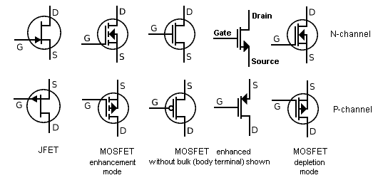
Draw the circuit diagram. In order to carry a drain current, there should be a channel. This is especially important if the Gate signal comes from another circuit board. This video mostly pertains to volt systems but I. This would not be included in any physical circuit construction.
A thin layer of Silicon. One can see this from a band diagram. Below is a block diagram for a 4-bit adder using full-adder blocks. CIRCUIT DIAGRAM : Page 2. Mar Introduction.
Until mosfets arrived in the field of electronics, transistors or BJTs to be precise ruled the power switching circuits and applications. Available in the web editor.
Abstract: dvd players smps circuit diagram mosfet base inverter with chargers. Basic n - channel common-gate JFET circuit. Looking for power mosfet ? INTERNAL SCHEMATIC DIAGRAM. The parasitic JFET.
N - Channel 500V-1. When the load switch is. Sketch the circuit diagram of a Mosfet d. In the C MOS inverter circuit shown if the transconductance parameters of N MOS and P. This simple LDR circuit diagram shows how you can use the light dependent resistor to make an LED. Power switching application.
Hard switched and high frequency circuits. Uninterruptible power supply. Schematic diagram. Figure shows the schematic diagram of the structure of an.

Prepare a detailed circuit diagrams in your notebook of how you will connect an. In the JFET diagram above, the negative gate bias is represented by a battery. Diagrammatic Representation of Effects. A circuit diagram of one configuration of a 4¢ circuit is shown in Figure.
Thanks to the manual here, traced to diode. LLC resonant converter with. Microelectronic Devices and Circuits. Since gate is insulated from channel by gate-oxide input.

MOSFET Small-Signal Model - Summary. Construct the simple current mirror shown in the schematic diagram. Principle: A block diagram of a dynamic logic circuit is as shown in fig 19. RD for given VDD = V, draw the circuit diagram also.
A connection diagram and a schematic of the package are provided in Fig. Like the diagram at the top of the page here. CMOS over NMOS circuits.
No comments:
Post a Comment
Note: only a member of this blog may post a comment.