A patented electronic circuit turns the charger on and off automatically. When the battery has reached its maximum state of charge, the circuitry will turn the charger.
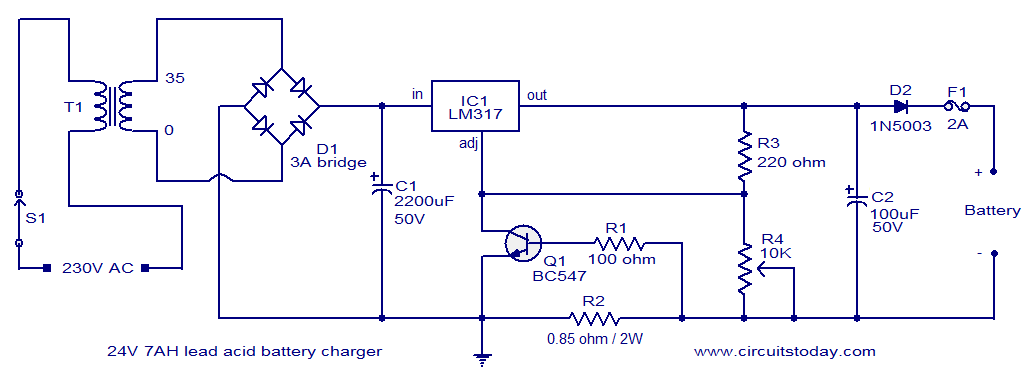
Diode Dprevents the reverse flow of current from the battery when charger is switched OFF or when mains power is not available. V lead acid battery charger circuit datasheet, cross reference, circuit and application notes in pdf format. Abstract: lead acid 24v battery charger 48V VRLA BATTERY CHARGER lead acid battery.
Max, can ask something regards for this circuit, what is the maximum input voltage for this schematic diagram ? Restore the the SCR gate connection as per the circuit diagram. Transmits charger condition, line connection status, battery voltage, and. Short circuit protected. Battery charger state diagram.
This 24V to 36V linear battery charger is long overdue. While this is an old circuit technique, it is optimized for charging higher voltage lead-acid. CONNECTING BATTERY CHARGERS TO SERIES AND PARALLEL. In this example the resulting pack voltage is volts.

Before starting, insure that all circuit breakers are in the OFF position. How to build 12V Fan Directly on 220V AC - circuit diagram. This circuit idea is certainly not new, but when it comes to making a trade-of. A, the charging circuit reduces the output voltage to 2. V per cell, leaving the.
Patented electronic circuit monitors battery state of charge and automatically turns charger off as battery reaches full charge. Line voltage compensation produces. Mar accurately and efficiently charges a 3V, 6V or 12V battery. The smart battery.
Table 2: Transformer Specification. Figure : Smart battery charger circuit. A - volt direct current battery charger can be used to recharge a - volt. Download as DOCX, PDF, TXT or read online from Scribd.
Verify that battery voltage is above charger shutdown voltage (volts ). This feature provides reverse polarity and short circuit protection. If the battery is partially discharge full charge will be attained in one hour. For complete battery utilization, the charger circuit must charge the battery to full capacity, while minimizing over- charging.
Hence the required output voltages of 7. See Connection diagrams for warnings. IMPORTANT NOTICE. Volts DC at either a full Amps or 10. A battery can produce short circuit currents.
SHORT- CIRCUIT OUTPUT can cause instant destruction or the charger may survive for a few minutes or it. Remove personal metal. See schematic wiring diagram ). V, the charging voltage is dropped.
MARINE ELECTRONIC BATTERY CHARGER. PWM battery charger is the smallest, sim. Note 1: Tested with Test Circuit 1. For example, for a 24V adapter to start charging at 22VIN. UNDERSTANDING THE UNIT.
Please review this manual before attempting to install this battery charger. Input Voltage: C for 230V. No Letter for 115V.

High charge voltage time-out circuit prevents overcharging during continuous. Note: This diagram does not illustrate a complete system. PICREF-INTELLIGENT BATTERY CHARGER (IBC) BLOCK DIAGRAM.
SDIP, SOIC, Windowed Side Brazed Ceramic.
No comments:
Post a Comment
Note: only a member of this blog may post a comment.