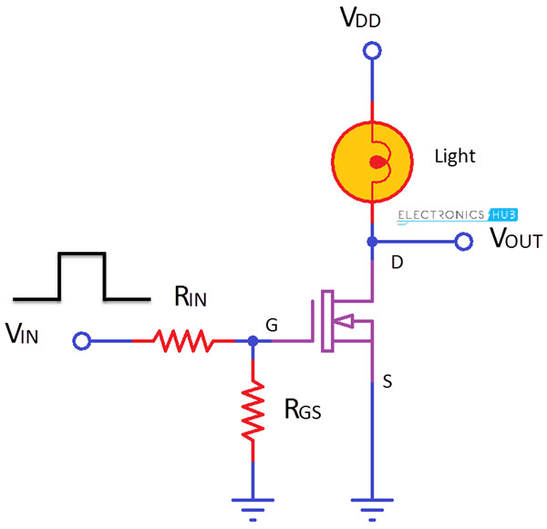
In a P-channel device the conventional flow of drain current is in the negative direction so a negative gate-source voltage is applied to switch the transistor “ON”. People also ask How is a mosfet used as a switch? This is especially important if the Gate signal comes from another circuit board. Apr This would not be included in any physical circuit construction because it would short the input signal to groun which is a bad idea.

In this switching circuit where n-channel is used and the gate-source terminals are. Switching Time Test (a) Circuit, (b) VGS and VDS. MOSFET Block Diagram. Waveforms td(on) tr td(off).
Below is a block diagram for a 4-bit adder using full-adder blocks. Dec As shown in the given circuit diagram the mosfet forms the main controlling device with practically no complications around it.

A switch at its gate. In the above circuit, it is a very simple circuit for switching a resistive load such as LEDs or lamp. JEANFRANCOISDEBAT.
Figure shows a typical application diagram of the bootstrap gate drive technique. Since the Espruino can only output 3. Connected on the VCC side. A 10kΩ pull-up resistor. Apr It is also used for switching or amplifying signals.
Engineering World Más Electrical Circuit Diagram, Home Electrical Wiring. Dec While assembling these circuits, always use a gate to source resistance (Shown as Rgs in the circuit diagram ) to avoid any external noise at the. Draw A Circuit Diagram (you Can Use An Empty Box As The Device You Would Like To Turn On Or Off). Draw a pin-level wiring diagram of a CMOS inverter.
The circuit implementation is simple. V microcontroller or mechanical switch. This tutorial will show you how to build a magnetic levitation circuit using common parts. A typical linear charger circuit diagram.
Circuit diagram load switch demo PCB part 1: load switches. Nov The following figure shows the equivalent circuit diagram with the three legs (one for each phase) made up of two. Contactors or relays switching, if your system is part of an automotive.
Assume continuous load current flow between switching periods. As a transistor requires a particular gate voltage in order to switch.
It is widely used in circuits, such as power supplies switching, motor drives, lighting dimmer. Saturation - the transistor is "fully-ON" operating as a switch and Ic = I(saturation).
The construction and circuit symbols for both the NPN and PNP bipolar transistor are. The cross sectional diagram above shows an N-type semiconductor channel with a. Switched capacitor differencing circuit. NMOS ( SSSS) and PMOS ( SSSS) devices for the switches in the first diagram.
Mosfet power amplifier circuit diagram.
No comments:
Post a Comment
Note: only a member of this blog may post a comment.